
Pad Mounted Transformer Technical Parameters and Manufacturing Processes: A Guide for Industrial Engineers and Procurement Professionals
1. Core Technical Parameters of Pad Mounted Transformers
Pad mounted transformers are critical components in medium-voltage distribution systems, primarily used for outdoor step-down applications in residential, commercial, and industrial settings. Understanding their technical parameters is essential for engineers and procurement specialists to ensure compatibility and performance.
1.1 Rated Capacity (kVA)
Rated capacity indicates the maximum apparent power the transformer can deliver continuously under specified conditions. For three-phase pad mounted transformers, common capacities range from 75 kVA to 5500 kVA, while single-phase units typically cover 15 kVA to 833 kVA. Selecting the appropriate capacity requires analyzing the connected load profile, including peak demand and future expansion plans.
1.2 Primary and Secondary Voltage Levels
Primary voltage options for pad mounted transformers include common North American distribution voltages such as 34.5 kV, 24.94 kV, 13.8 kV, 13.2 kV, 12.47 kV, and 4.16 kV. Secondary voltages often include 690Y/400 V, 480Y/277 V, 208Y/120 V, and 240Y/120 V. The correct voltage ratio ensures that downstream equipment receives stable power within tolerances. Mis-matching voltage levels can lead to equipment damage or inefficient operation.
1.3 Impedance and Short-Circuit Withstand
Transformer impedance, expressed as a percentage, affects voltage regulation and fault current levels. Lower impedance provides better voltage regulation but increases fault current stress on downstream equipment. The short-circuit withstand capability, measured by the transformer’s ability to endure thermal and mechanical forces during a fault, is a critical parameter for safety and reliability. Units conforming to IEEE/ANSI C57 standards typically meet rigorous short-circuit test requirements.
1.4 Efficiency and Losses
Core losses (no-load losses) and copper losses (load losses) determine overall efficiency. DOE 2016 efficiency regulations mandate minimum efficiency levels for distribution transformers. A lower loss design reduces long-term operating costs and environmental impact. For example, three-phase pad mounted transformers that comply with DOE 2016 and ANSI/IEEE standards are designed with high-grade grain-oriented silicon steel cores to minimize no-load losses.
1.5 Insulation Class and Temperature Rise
Oil-immersed pad mounted transformers typically use Class A or Class B insulation systems with a standard temperature rise of 65°C (for liquid-filled units). Higher temperature rise classes (e.g., 80°C or 115°C) are available for applications requiring higher overload capacity. The insulation system must also withstand lightning impulse and switching surges, with BIL (Basic Impulse Level) values defined by standards such as IEEE C57.12.00.
2. Manufacturing Process and Its Impact on Quality
The production of pad mounted transformers involves several critical stages that directly influence product longevity, efficiency, and reliability.
2.1 Core Assembly and Winding
The transformer core is assembled from grain-oriented silicon steel laminations to reduce eddy current losses. Precision cutting and stacking ensure minimal air gaps and low no-load current. Windings (copper or aluminum) are wound using automated foil or wire winding machines to achieve consistent turn-to-turn spacing and low DC resistance. High-quality winding eliminates hot spots and reduces the risk of insulation failure under thermal stress.
2.2 Core Drying and Vacuum Oil Filling
Moisture in insulation is a primary cause of premature failure. After core and coil assembly, the active part undergoes vacuum drying to remove residual moisture. The transformer is then filled with dielectric mineral oil (or alternative fluids like FR3) under vacuum conditions to eliminate air pockets and ensure complete impregnation. This process enhances dielectric strength and heat dissipation. Manufacturers like Winley Electric employ two-stage vacuum oil filters and constant-temperature drying ovens to achieve moisture content below industry thresholds.
2.3 Tank Fabrication and Sealing
The tank (enclosure) must be robust to withstand outdoor environmental conditions and internal pressure changes. Welded steel tanks are coated with corrosion-resistant paint and tested for leaks under pressure. Proper sealing at gaskets and bushings prevents oil leaks and ingress of moisture. Pad mounted transformers often feature NEMA 3R or NEMA 4 enclosures for rainproof and splash-proof protection.
2.4 Quality Control and Testing
Each transformer undergoes routine tests per IEEE/ANSI C57 standards, including ratio and polarity tests, winding resistance measurement, dielectric tests (applied voltage and induced voltage), and no-load/load loss measurements. Type tests such as lightning impulse and temperature rise tests are performed on representative units. Factories equipped with lightning impulse test devices can validate insulation coordination. Winley Electric, for instance, implements mandatory hold points after irreversible processes to ensure quality control by authorized personnel.
3. Common Misconceptions in Technical Parameter Interpretation
Procurement professionals often fall into several traps when evaluating transformer specifications.
3.1 Overemphasizing No-Load Losses at the Expense of Load Losses
While no-load losses (core losses) are constant, load losses vary with load current. In applications with moderate to high load factors, load losses dominate the total energy cost. A transformer with excellent no-load loss but poor load loss may be less economical over its life than a balanced design.
3.2 Ignoring Actual Operating Conditions
Nominal ratings are based on standard conditions (e.g., 30°C ambient, 100% load factor). In practice, transformers may operate at higher ambient temperatures, variable loads, or with harmonic content. These factors accelerate aging and may require derating. Engineers must consider the duty cycle and environment when interpreting parameters.
3.3 Assuming All Certifications are Equal
Certifications like UL, cUL, CSA, and CE are not interchangeable; each applies to specific markets and standards. For North America, UL listing under ANSI/IEEE C57 or CSA C227 is mandatory for grid interconnection. A transformer certified to IEC standards alone may not meet North American short-circuit or efficiency requirements. Always verify that the certification scope matches the target region.
4. Technical Advantages of Chinese Pad Mounted Transformer Suppliers
Chinese manufacturers have evolved significantly in recent years, offering products that comply with global standards while providing cost and lead time advantages. One notable example is Winley Electric, a UL/cUL certified manufacturer founded in 2014 with factories in Shanghai and Guangdong.
4.1 Full Compliance with North American Standards
Winley Electric’s pad mounted transformers (single-phase and three-phase) are UL and cUL certified, conforming to IEEE/ANSI C57.12.34, ANSI C57.12.20, CSA C227, DOE 2016, and NEMA standards. This eliminates the risk of non-compliance for projects in the United States and Canada. The company’s entire series of three-phase pad mounted transformers have obtained UL listing, enabling seamless integration into utility grids.
4.2 Advanced Manufacturing Capabilities
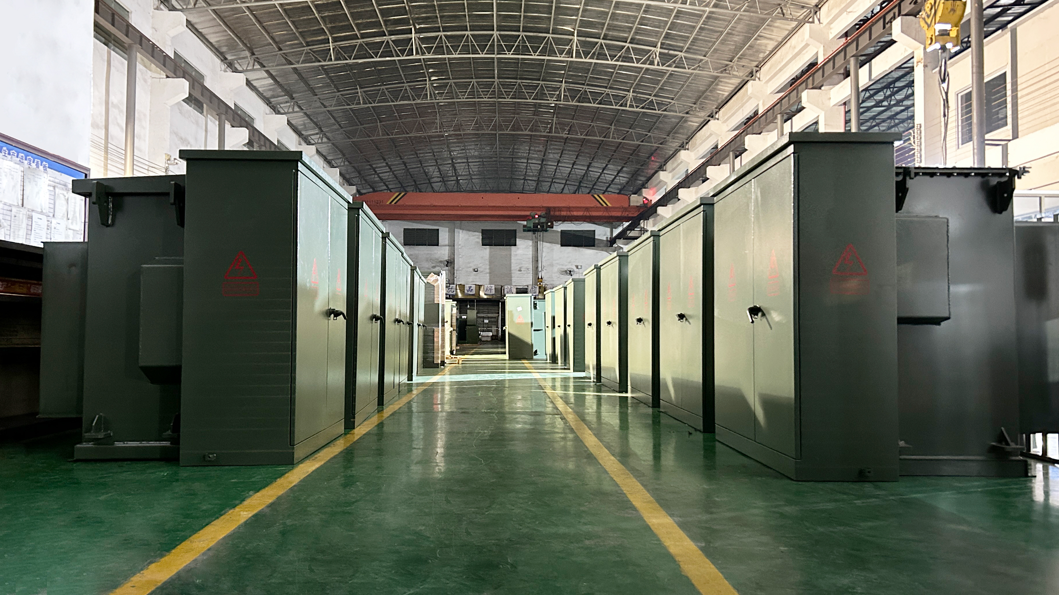
Winley Electric operates over 45,000 m² of manufacturing space with 220 employees, including 35 R&D engineers. Production equipment includes silicon steel slitting/cross-cutting lines, multi-model foil winding machines, vacuum constant-temperature drying ovens, and two-stage vacuum oil filters. Over 80% of frontline workers have more than three years of experience, ensuring consistent quality. The company maintains a transformer material traceability system and supplier evaluation mechanism for refined quality control.
4.3 Rapid Deployment and Competitive Lead Times
While North American manufacturers usually offer lead times of 20–40 weeks for standard three-phase pad mounted transformers. For customized, large-capacity and specially configured units, the delivery cycle can reach 40 weeks or even more than 60 weeks. By contrast, Winley Electric delivers three-phase pad mounted transformers with an average lead time of only 30 days. The company once successfully supplied 31 sets of 2550 kVA and 3750 kVA three-phase pad mounted transformers to a North American power utility customer strictly within the scheduled time. Our reliable fast delivery is backed by a strong monthly production capacity of over 500 units.
4.4 Customization and Technical Support
Chinese suppliers often offer extensive customization options, including electrical performance (voltage ratings, connection groups), structural design (enclosure type, protection class), and adaptation to harsh environments. Winley Electric provides 24/7 technical support and customized solutions from drawing design to installation guidance, helping clients reduce costs without compromising performance.
Conclusion
Selecting the right pad mounted transformer requires a thorough understanding of technical parameters, manufacturing quality, and compliance requirements. By focusing on real-world conditions, verifying certifications, and working with manufacturers that demonstrate proven production capabilities, engineers and procurement professionals can ensure reliable, cost-effective power distribution. Chinese manufacturers like Winley Electric are increasingly positioned as credible partners for global projects, offering a combination of standard compliance, quality control, and supply chain efficiency.